Linetypes
Home | Linetypes
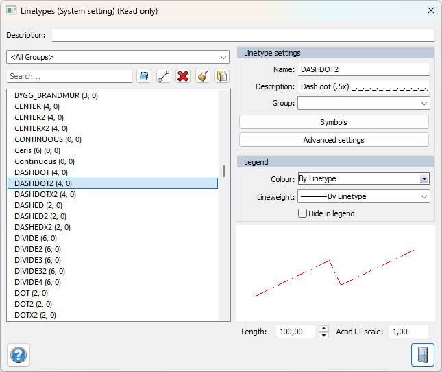
Table for editing line types.
Allows you to delete and rename line types from the table, the global line type is selected under Settings. By opening the table and pointing to the desired line type and then selecting Delete, the line type is removed from the list.
AutoCAD line type
To facilitate data exchange between Topocad and AutoCAD and to allow Topocad to easily draw line types that can be broken at the line's break points, AutoCAD's line type definitions are supported.
Line type scale
The line type scale is used in combination with the drawing scale and only affects AutoCAD's line types. The default line type scale that applies when creating new drawings is set in the system settings. The settings are under Home | System Settings - Screen.
The current drawing scale of a drawing is specified in the drawing properties. This is the scale that affects the drawing of AutoCAD line types in the current drawing.
Line type generation
The line type generation determines how the drawing of the line type will handle the drawing of the line. This setting only affects line and polygon.
The value of the line type generation is set on each object and the drawing is controlled by this value for the current object.
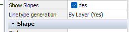
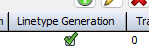
Below Properties Below Layers
When line type generation is turned off, the line type is drawn between each line segment, and the line's break points are always visible. When line type generation is turned on, the line type is drawn uniformly over the entire line and does not take the line's break points into account.
Current line type generation
The current line type generation on an object is changed via the object properties.
Edit symbols on line type
The symbol button allows you to edit the placement and direction of symbols in relation to lines, you can control which direction a symbol should point.
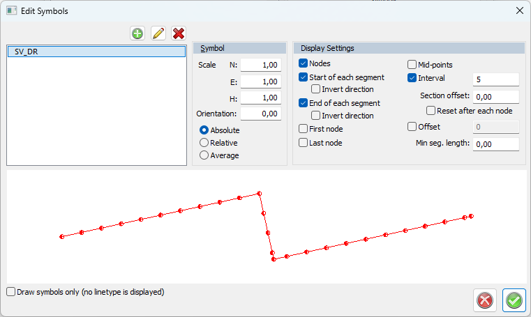
Symbol section:
Scale: Direct symbols by specifying a scale, enter N, E, and Z.
Orientation: Rotate the symbol as desired.
• Absolute: Display the symbol exactly as it was created.
• Relative: Display the symbol in relative terms on the line segment where the symbol is located.
• Average rotation: Displays the average rotation between the previous and following line segments where the symbol is located.
Settings section:
Nodes: Choose to display symbols on all nodes.
Start/end of each segment: Choose to display symbols at the start or end of each new line segment, or both.
First/Last node/Midpoint: Choose to display symbols at the first/last node or the midpoint of the line segment, or both.
Interval: Determine the distance between symbols, with the option to draw symbols per meter.
Section distance: Specifies the symbol placement on the side. Right is positive, left is negative. You can also check if this should be reset after each node.
Side dimensions: Position side dimensions outside the line segment.
Advanced
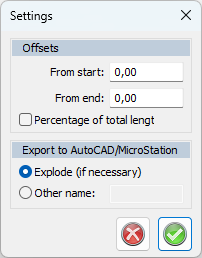
Start/End Line Type: Specifies where a line starts/ends and where it should be visible on the drawing.
Export to AutoCAD/MicroStation: Provides the option to rename during export (before the file is exported to the CAD system).