Insert sections
Drawing|Sheet|Insert sections
|
Command |
Description |
|
|
|
|
|
|
|
|
|
|
Longitudinal section entry. |
|
|
How to get the size and scale right. |
|
|
General settings for inserting into the drawing |
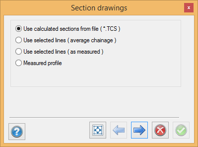
There are four ways to create and insert section drawings:
- Inserting created cross sections
- Creating sections from lines in the drawing
- Using measured sections
- Using measured profiles
Inserting calculated sections
For insertion of created sections (TCS files)
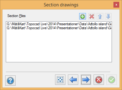
In this dialogue box, you select the section files you want to place in the drawing. You can use one or more created sections at the same time, but they will use the same section. If they are created along the same road line this is fine but if not they will show two different sections for the same section in the drawing. Use the up and down arrows to select the order. If you intend to insert two or more cross section files at the same time, they will need to have the same created section and section interval.
See the image above for details of how to enter information in the drawing.
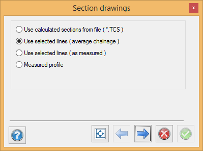
Section from lines in drawing
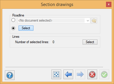
The procedure is as follows:
- Enter the roadline or select it in the drawing.
- Select the sections crossing this road line, click Next. Refer to DRAWING.
Calculate and set out the measured sections
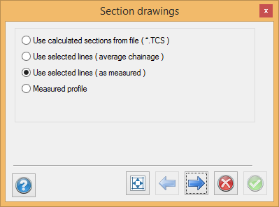
The procedure is as follows:
- Use the selected lines as measured option (see screenshot)
- Enter the roadline or select it in the drawing.
- Select the sections crossing this road line, click Next. Refer to DRAWING.
Calculate and show measured profile
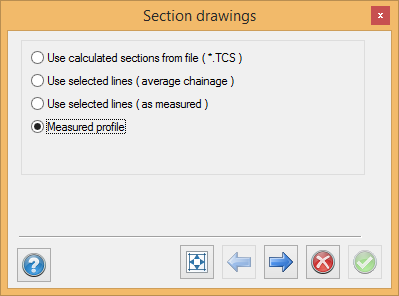
The procedure is as follows:
- Use the measured profile option (see screenshot)
- Select the measured profile.
- Select the insertion method. Refer to DRAWING.
Drawing scale and size
Use a drawing sheet and views:
- Use a new blank drawing.
- Insert a drawing sheet with the scale and size you want in the drawing (if there are no drawing views, continue from 3-4)
- Place a new drawing view in this drawing sheet.
- Select the scale for it.
- If you know that you will need more drawings, repeat these steps and place the drawing views next to one another.
- Continue with the next step.
Insert in the drawing
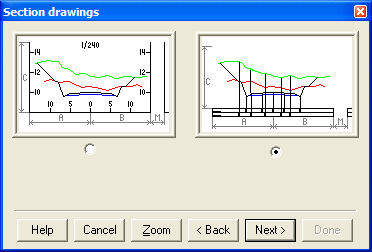
There are two main methods, which mainly differ in terms of the layout. We call them the bucket and the form.
|
|
|


|
Method: |
Method: |
Description |
|
Select method and type of view |
||
|
It is possible to select the section size and the margin between them. |
||
|
Text information, size etc.. |
||
|
Select layers and information |
||
|
|
Select which objects are to be displayed |
|
|
What sections, number, start section, intervals, sections per column etc... |
Method selection

Select the method you want to use to insert your sections:
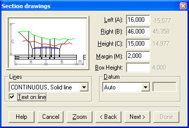
Layout
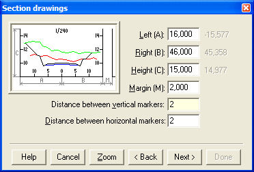
Enter the values for different distances for the section. You will find the maximum value of any of the sections made/created in grey to the right.
Left (A)
Left-hand side of cross section from the centre point.
Right (B)
Right-hand side of cross section from the centre point.
Height (C)
The maximum height for any section.
Margin (M)
The margin between the cross sections in the drawing.
Distance between markers
The distance between the markers for the vertical and horizontal side.
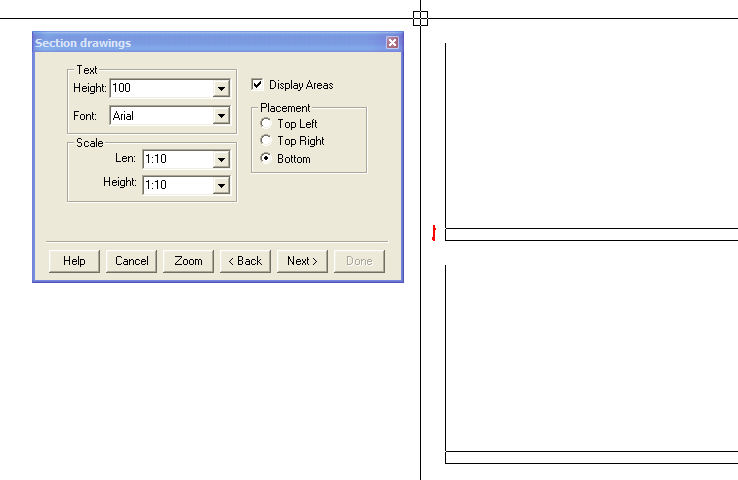
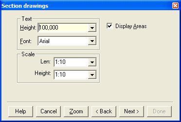
Text
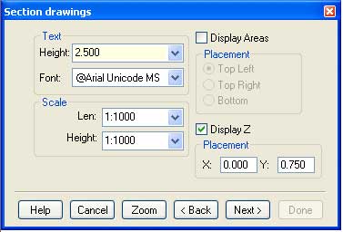
Select the text height and font. It will sometimes be difficult to identify the correct size. Try clicking once in the drawing to obtain an idea of the size. If you have selected "Display areas" and "Bottom" as shown, you will see in the drawing how high the bottom line is. This is shown by the red dot in the screenshot below.
Display Z: The coordinate refers to the middle point on the theoretical layer in the first document that has been indicated in the command. The placement of X and Y shall be between 0 and 1.
0.0 corresponds to the upper left margin and 1.0 corresponds to the lower right margin.
Scale
The scale is used for different scales in the sections.
Placement
Where the area text is to be placed.
Field
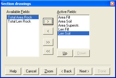
This window is only used if you are using areas. All areas used in the cross sections will be available, including those fields you created yourself.
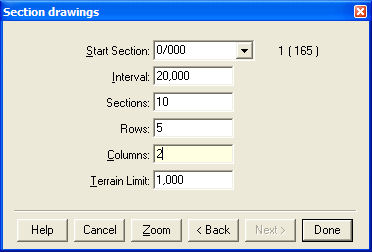
Sections
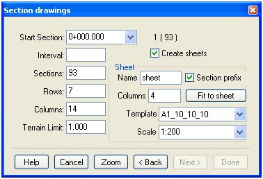
Select how many and which sections you want for each drawing. You can see their size by clicking once in the drawing. You need to fit them into the drawing view you have placed in the drawing.
Sections
Total number of sections for each drawing
Rows
How many rows you want to use in your drawing.
Columns
For your information only, shows how many columns there will be depending on the total number and how many rows you are using.
Terrain limit
The terrain limit specifies how far outside the maximum theoretical section the sections will be on each side.
Create sheets
Check if you want to create sheets.
Name, Columns, Template
The settings controls the name of the sheets, number of columns, sheet, template and scale of the drawing view.
If the Section prefix is checked, a start and an end cross section will be added as a prefix to the name. If the selected template has more than one view only the first view will be used.
The button Fit to sheet sets the highest amount possible of rows and columns that fit in selected template and scale.
When you have done all this, place your sections in the drawing. You can place the next set of cross sections in the next drawing view immediately. If you are running out of drawing views, place the sections in the blank drawing and create drawing sheets afterwards.
Form method
This method uses more information for each section.
Layout
Select the distances and enter them in the dialogue box.
Box height
The height for each box and form below the section.
Lines
Line type for the form. If you want the text to be placed on the line, select this option.
Date
Position for the first form/box according to the sections. The options are automatic, distance or actual height, where distance represents the distance between the box and the form.
Text
Select the text height and font and whether you want the areas to be displayed.
Field
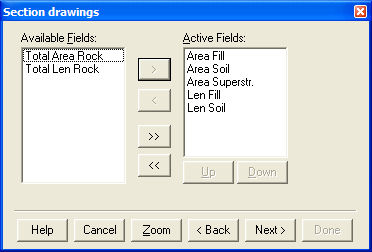
This window is only used if you are using areas. All areas used in the cross sections will be available, including those fields you created yourself.
Selecting layers
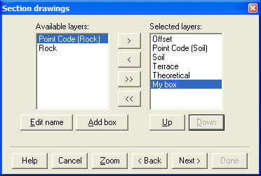
Select the layers (forms) that you want to use for each cross section. The name can be edited when they are on the left-hand side. You can add boxes that will be empty. The information to be added here is the height of each break point in the selected layer.
Sections
Select how many and which sections you want for each drawing. You can see their size by clicking once in the drawing. You need to fit them into the drawing view you have placed in the drawing.
Sections
Total number of sections for each drawing
Rows
How many rows you want to use in your drawing.
Columns
For your information only, shows how many columns there will be depending on the total number and how many rows you are using.
Terrain limit
The terrain limit specifies how far outside the maximum theoretical section the sections will be on each side.
When you have done all this, place your sections in the drawing. You can place the next set of cross sections in the next drawing view immediately. If you are running out of drawing views, place the sections in the blank drawing and create drawing sheets afterwards.
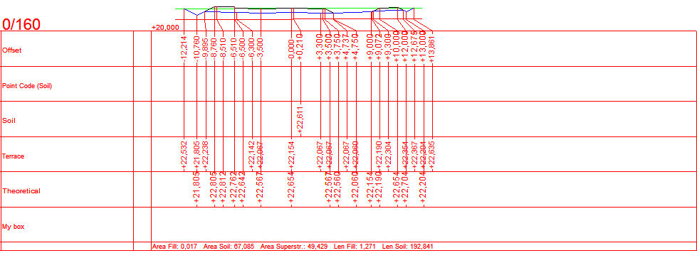
Cross section example: