Create DTM
Drawing|Terrain|Create DTM
 The DTM (Digital Terrain Model) can be used for various calculations, e.g. volume calculations and contour lines. The Topocad DTM is a triangle model which creates a triangle using the three closest points in each case. However, there are some exceptions.
The result will be a set of triangles: from above they look like just triangles, but each point will have a height attributed to it.
Select object:
Select the objects you want to use to create a DTM. To select objects, see Select entities
It is possible to hide, freeze or make layers invisible to ensure that the wrong objects cannot be selected. It is important that you do not select co-ordinates with a height of zero as this will create a gap in the DTM.
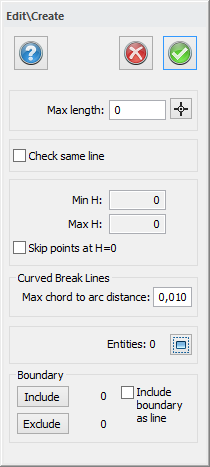
Max. length:
This length limits the maximum length of a triangle side on the outer side of the model. Triangle sides that are longer than this will not be included in the model. This is a quick way to limit the editing of the model. You can either type in a value, or select one by clicking in the drawing. Click on two different points. The length between them will be the maximum length:
Check same line:
By default this is unchecked. This limits the triangle so it is impossible to create a complete triangle with all three points on the same surveyed polyline. It will also calculate using polylines as break lines.
Max. Z/Min. Z:
This displays the maximum and minimum heights of the selected objects.
Skip Z = 0
Selecting this box will exclude all points which have a height of 0. (These will usually be theoretical points).
Curved break lines
This feature is used to calculate break lines in the DTM. It divides the radius at various intervals so that each one can be used to calculate triangles. Creates really accurate models.
Polygons
You can choose to include or exclude polygons.
Boundary
If the box "include boundary as line" is checked, the selected (if there are any) boundary will be included as a line in the model. The boundary's points will be included as points in the model if the box is unchecked. When the boundary is included, the Z values collects from the boundary. If the boundary includes as points, the Z values are calculated on the basis of the model, as the models looks before it cuts off at the boundary.
If corrupt structure is found
If you stop the creation of the DTM you will be zoomed in on the problematic part of the DTM structure.
See also:
Note:
When creating the DTM, check that it does not contain duplicate points as this can create errors. If you have trouble creating a DTM, you can export the objects to a co-ordinate file and then import it to a new blank drawing and create the DTM from that.