Co-ordinate grid
Drawing|Sheet|Coordinate grid
 The co-ordinates grid is created in the drawing or drawing sheet. The co-ordinates grid can be placed in the same layer as the drawing frame and drawing stamp.
The co-ordinates grid can be inserted in a drawing sheet. You will then need to select which drawing view to work in. The co-ordinates grid will adopt the scale and create a co-ordinates grid of the right size.
To create a co-ordinates grid:
- Select or create the layer for the co-ordinates grid.
- Select Create|Coordinate grid.
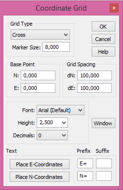
- Select which type of co-ordinates grid you want to use. You can select from three different types - cross, net and frame.
- Select size for the cross (this is not necessary when selecting net). Note that these distances are in metres. ). The command identifies the set drawing scale and will suggest sizes relative to the drawing scale. If you want the size of the cross to be 8 mm on the drawing you will need to select the following heights for the different scales:
- Drawing scale: Cross in mm on the plot. Size in metres:
- 1:100 8 0.8
- 1:400 8 3.2
- 1:500 8 4.0
- 1:1000 8 8.0
- 1:2000 8 16.0
- 1:10000 8 80.0
- Select the base point. The base point is the point from which the numbering of the grid is to be calculated. The default value is X=0, Y=0.
- Select the distance you want to have between the cross, net or marks in the frame. ). The command identifies the set drawing scale and will suggest sizes relative to the drawing scale.
- Select the font you want to use.
- Select the height of the text. Note that the height is in metres.
- Select where you want the text to be printed and also any prefixes or suffixes required.
- Click on the window and select which area you want to create the co-ordinates grid to appear in.
- Click OK. The grid will be plotted in the drawing.
See also