User Defined Coordinate system
Drawing|User Defined Coordinate system
Shift + B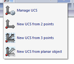
A baseline is an effective way to interpret different objects. To create a baseline you have to select the origin and the direction for the baseline. There are four different types of UCS - Local coordinate system can be specified.
To activate the baseline: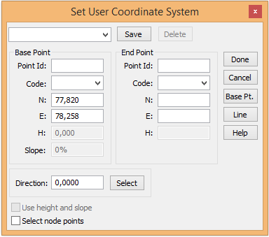
- Select Drawing|User defined Coordinate system
- You can now select a previously saved baseline by selecting the name from this list. To create the baseline:
- Select the point for the new origin. You can use snap commands or enter the value manually.
- Select the direction for the X (north) axis.
- Save the baseline by entering a name in the upper box.
To activate the baseline, tick Activate. You will notice that as soon as you have selected the origin and direction the dialogue disappears. However, if you forget to activate the baseline you will not lose the settings.
The baseline will be displayed with the crosshair, which will have the same direction as the baseline.
The baseline can also be used in Misc|Co-ordinate toolbox and for point difference.
Selected co-ordinate system is also shown as co-ordinate axis in the systems origin or in the windows lower left part, if the origin not is visible.
To deactivate the baseline: 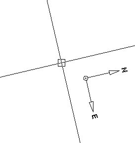
- Select Baseline
- Select Global from the list.
- Click OK.
TIP! If you enter local co-ordinates from the baseline, enter them in the Co-ordinates toolbox (View|Toolbox|Co-ordinates)
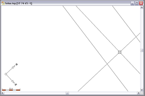 Current coordinate system is shown as a separate toolbar. Coordinate input in designing line, dot, circle, edit line properties (point and circle) and edit as the text is done in the current coordinate system. Name of the local coordinate axes are under System Settings | Axles Current coordinate system is also shown with coordinate axes in the system origin or the lower left part of the origin is not visible.
Create new UCS 2D
Drawing|User Defined Coordinate system
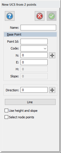
Enter the base point of the coordinate system and the direction of base point axis, it shows the extent to which the direction of the x-axis is. This is the same as the baseline command Topocad 15 except that you can not remove baselines (UCS) here.
Create new UCS 3D
Drawing|User Defined Coordinate system
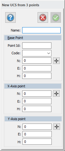
Specify the x and y-axis to create 3D plane. The difference between UCS 2D- and 3D is that you specify the Y-axis to view the item in 3D format. This provides an opportunity to draw the coordinate system entirely in 3D. Create a UCS in 3D by first pointing out the origo, then the extent of the X-axis and Y-axis.
Create UCS from plane objects
Drawing|User Defined Coordinate system
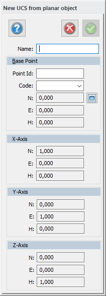
A plane object/ plane entities can be lines, polygons, circles, text and symbolic references. For this feature you may use direction of extension of the entity. The point selection replaces the x-axis. The X-axis indicates which direction the nearest point is and that the X-axis will assumes. It also chooses which point and entity it concerns.